Wednesday, December 10, 2014

Last Carbon on Mainsheet Beam

After a bit of fairing to level any previous layup seams, I have applied the final layer of carbon.


This is a 300gm/sqm bidirectional sleeve. The sleeve went on before wet out.  It looked pretty hard to wet it out and then slide the slimy, slick tube over the beam.  I rolled and squeegeed multiple coats on the beam, as I was a bit worried about full saturation of cloth this heavy. 


There was some creative clamping going on.  I skipped vacuum bagging to avoid wrinkling.  The sleeve can be stretched pretty tight by hand.

Finishing will require fill coats of epoxy and sanding smooth.  The worst of the process will be sanding the gathered ends to blend them into the end shapes.  


Task time: 12 hours
Total project time: 346 hours

Monday, November 17, 2014

Inlay of Aka Washers

One of today's small tasks was routing out the bulkhead beams to allow inlaying the carbon plate washers.


The template was made with a 3 inch hole saw.   This was slightly bigger than the 75mm washer and it left a bit of room for glue.  The template was aligned/centered by "stacking" the components.  The G10 tube went in the hole, the washer went over the tube and the template around the washer.


The washer dry fitted.

A flush trim bit removed the material from the beam.   This is another task that an experienced build would have knocked out straightaway, but it took me a little head scratching until I came up with the solution.

Task time: 3 hours
Total project time: 334 hours

Saturday, November 15, 2014

Mainsheet Beam in Vacuum Bag


This is just an extra shot I had of one of the many vacuum baggings of the beams. The envelope is made of plastic packing tubing.  Only the ends need to be sealed on the tube, simplifying matters and reducing the potential for leaks.  I have been sealing the ends of the tubes with these plastic snap-together flanges from ACP Composites.  They are cheaper and more consistent than bagging tape.


The packing tubing can be found at ULINE and other places.

Thanks to Dan Newland at Pegasus Aeromarine for turning me on to packing tubing.


Main Bulkhead Work

I have been trying to do several small projects in parallel.   One of the recent projects are the main bulkheads that are at both ends of the main cabin.   These stations have reinforcing planks where the aka cross beams will bolt through the hull.

The unfinished area in the middle gets cut out of the companionway after the bulkhead is in the hull. Until then, it is an extra bracing support.


The bulkheads are large enough that they came from two pieces of plywood.  After gluing the puzzle joints, I have coated both sides with three layers of epoxy.  The epoxy then got sanded back as smooth as I could get it, so it is now ready for final finishing.

The reinforcing planks will get epoxied to the bulkheads before being placed on the strongback.  The planks were shaped from templates that I had made a few months back.  I recently dry-fitted them to the bulkheads with screws through the back.  This allowed me to get the alignment correct and bore holes for the aka bolts.  The screw holes will get filled with epoxy later.   They will mar the less visible surface of the bulkhead a bit.   The screws will be used to accurately locate the planks when they are slick with glue and to help with clamping.


I left the epoxy coating off of the gluing surface of the bulkheads.  This will give an area for a primary wood to wood bond.  Probably not that critical, but it can't hurt.


The hole through the bulkhead gets a similar treatment to the akas.  A G10 tube is inserted and then there is a 75mm cplate washer that the bolt will tighten against.


Task time: 20 hours
Total project time: 331 hours

Monday, November 10, 2014

Mainsheet Beam Carbon Layups

Each side of the mainsheet beam gets about 12 layers of carbon.  These include uni, bi-directional and plain weave cloth.  It seems quite easy to wrinkle the cloth as it goes around the compound curves in the vacuum bag. As I learn, I tend to get less of this.  It is definitely not good since to get a smooth layer a wrinkle must be sanded a little bit, causing a small area of reduced strength.


A pattern for cutting cloth.


A typical layup applied to the beam before going into the vacuum bag.


I had to cleanup the nubbins with a router after a few layers that did not lay well into the groove.
Above, I am putting a few layers of scrap carbon back into the groove.  The dowel matches the size of the router and is used a clamp to compress the carbon.  I lashed the ends of the dowel around the beam to pull it tightly into the groove.


The dowel was removed after cure. I used packing tape to keep most of the new material off the surrounding beam. 


The  excess cloth has been trimmed and sanded.  This beam needs three more layers all the way around.


Each layup has quite a few steps including cutting the cloth, peel ply and breather, setting up a vacuum bag, wetting out and applying the cloth, peel ply and breather and getting it into the bag.

I have been wetting out the cloth on a piece of plastic.  I spread the epoxy over a layer and squeegee it back and forth.  Another layer of cloth goes on top and more epoxy.  At about three layers maximum, I  stop.  The plastic gets folded over the cloth.  I then squeegee the whole stack very firmly on both sides of the plastic envelope.  This forces air out and epoxy in.   The stack is then peeled off the plastic and laid on the beam where it is smoothed down tightly before the peel ply is smoothed over the top.  I tend to error on the side of too much epoxy.  The bag squeezes out the excess and you really want the carbon well wet out.

I am getting to the last layer which will be a bidirectional woven sleeve.  The sleeve should conform well and leave no seams.

Task time: 20 hours
Total project time: 331 hours

Monday, November 3, 2014

Boring Beam Mounting Holes


The Akas are attached to the main bulkheads with 18mm bolts.  The bolts are carried through the beam holes with a 20mm (3/4 inch) G10 tube liner.  I needed to bore the holes through the solid interior of the beams before the first layer of carbon cloth.  CNCed holes are marked on the plywood sides and I did not want to lose the reference marks under the cloth.

This is one of those seemingly simple tasks that takes a lot of pondering and worry.  The holes must be perpendicular to the beam all the way through and be accurately located so that they will mate properly with the bulkheads.

All kinds of little issues arise for consideration:

- How do you level an 18 foot beam with one end across a drill press table?
- There is not enough throw on the drill press without shifting the tables and re-leveling in the middle of a hole.
- How do you drill an accurate hole without using a drill press?
- The forstner bit is not long enough.
- The forstner bit extension does not fit a metric forstner bit correctly.
- The collar on the bit extension does not fit down into the  hole.

Finally found a drill stand for a hand drill, but would it be accurate enough?


G10 (Garolite) Tube


Setup that allowed a hole "almost" deep enough.  It would not reach the last millimeter, but the point of the bit went through for reference.


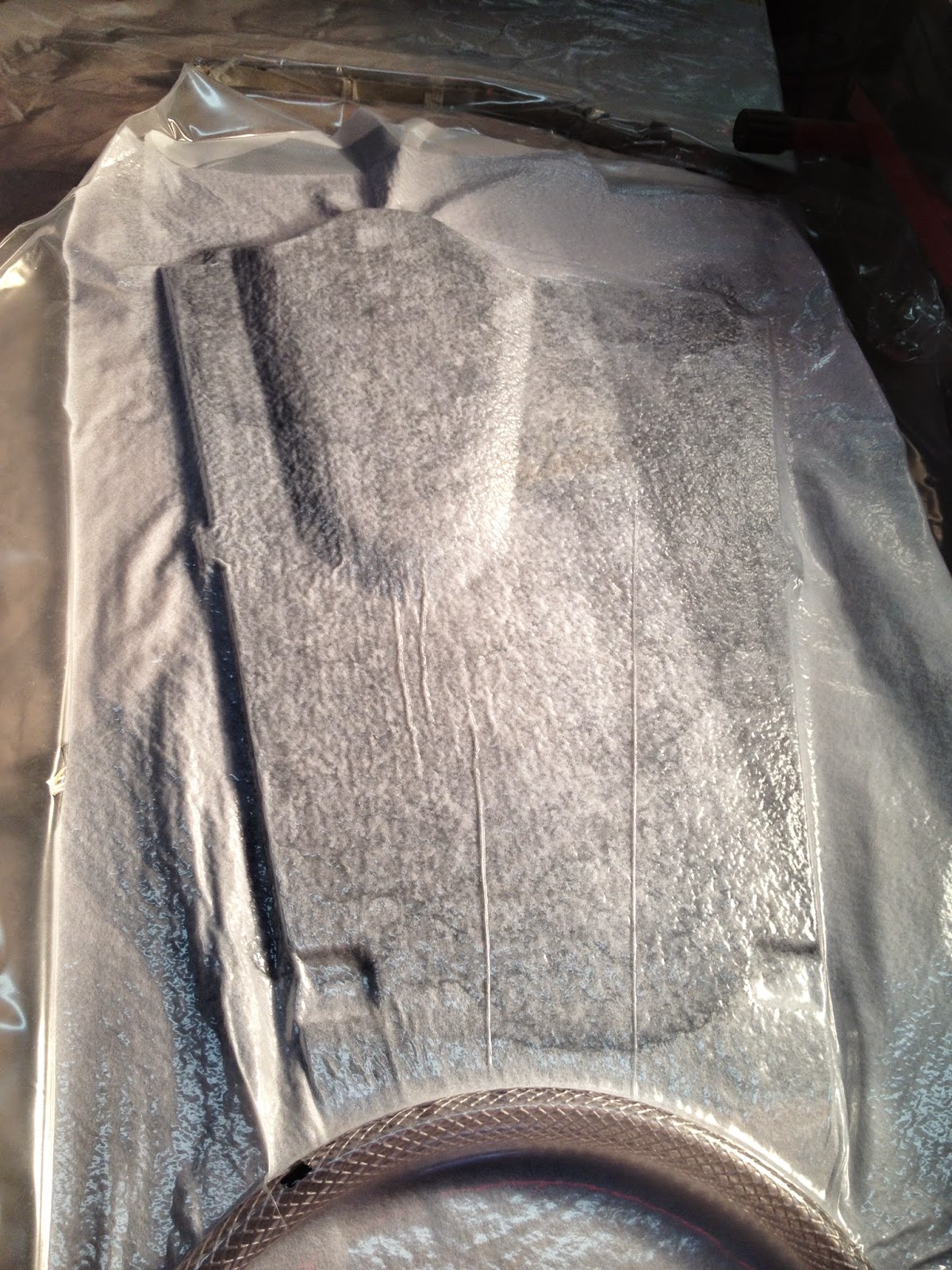
A 3/4 inch hole that has been sanded slightly with a dowel covered with sandpaper.  The 3/4 inch tube fits snugly through most of the hole.  There is a little extra room at the top where the original hole in the plywood is slightly bigger (2mm), but the tube is squared in all directions.


All you can say when you drill that first hole and it is OK is whew.


Task time: 2 hours
Total project time: 311 hours

Wednesday, October 29, 2014

Finishing Up Stay Bulkheads


I needed to seal the exposed "endgrain" of all the laminated layers.  I decided to try using a slit section of carbon sleeve.  The knit sleeves tend to wrap nicely around corners.


Here is a shot of the wet-out carbon which took the shape pretty well.


I then layed the final covering layer of cloth over the edge of the sleeve.


These pictures show the final coat after un-bagging.  There is a little bit of print through from the sleeve edge.  Those two laminations should probably be done separately, so that the fringe of sleeve can be sanded flush.

These bulkheads are about done, though they will need urethane coating for UV protection where they are exposed above the deck.


Task time: 5 hours
Total project time: 309 hours

Sunday, October 26, 2014

Fairing Stay Bulkheads


I decided I would fair in the cplate braces on the fore/aft stay bulkheads.  This would give it a little more finished look.  I added small strips of divinycell along the edges.

You can also see a flaw on the line to the left.  This was caused by using a piece of peel ply with a crease in it.  If you buy West System peel ply, get it bulk in rolls, not folded in bags.  Fiberglass Supply has a similar product in rolls.  It is impossible to get the creases to lay flat.


Once the epoxy was set, I sanded a bevel onto the foam.


There will be one light, cosmetic layer of carbon over the top.

Task time: 2 hours
Total project time: 304 hours

Monday, October 20, 2014

Q-Tip Test

When can you apply a hot coat of epoxy?  When must you sand before another coat?  Nick Schade, a noted kayak builder, has a simple test.


Nick has a many more useful building videos.

Sunday, October 19, 2014

Video Showing Shunting

Harryproa, the Atlantic proa people,  have put up a nice video showing shunting.  This a maneuver that is difficult for some people to visualize.


Bucket List is a new Harry design for a minimalist offshore racer.  They have an interesting idea of chartering them for famous offshore races allowing sailors to affordably compete in events that might be on their bucket list.

Carbon Work on Forestay Attachment

The fore/back stays are anchored on dedicated bulkheads which are strengthened with a combination of carbon plate and woven cloth.  There are three layers of cloth per side and then the cplate goes on. I believe the cplate was 18 layers making a total of 42 layers of reenforcement for the chainplates.


General Layout


Plate over carbon.  The nails act as locators.  Once glue has been applied the pieces are like a greased pig, so the nails allow you to find the proper position.


Plate faired and bagged.


Task time: 8 hours
Total project time: 302 hours

Thursday, September 25, 2014

Mainsheet Beam Cores Finished

 I spent several hours working to shape the laminated fir blanks.  The first order of business was to create an MDF template of the shape off of the drawings.   This required lofting a few points onto the MDF.  I then pulled a batten in line with the points against small nails. Next I hot glued the batten with support blocks to the MDF.  I could remove the nails and trim away excess material from the MDF sheet.  I then took the batten and MDF to the router table where I used a flush trim bit to cut fair curves.  This seemed more accurate than trying to sand fair curves to a line, especially on the concave side.


The batten flexed across nails.


Once the template was finished, I attached it to a laminated blank.  Using a saw and a belt sander (I still don't have a jigsaw), I removed excess material.  I then trimmed the blank to match the template using a 2 inch flush trim bit.  Almost all the excess has to be gone before using the large flush trim bit given the large load on the router when trimming over an inch and a half height (40mm) at once.


The finished template attached to the blank.


The blank cut and sanded close to the template.


With the blanks the correct shape, I moved on to rounding over the edges.  This is for aesthetics as well as getting carbon fiber to bond over the edges.  I also cut "nubbin" slots at each end.  These will keep the lashings that hold the blocks to the beams from slipping.


Finished cores after trimming, rounding over the edges and adding nubbins.


These are now ready for the first layers of carbon uni.

Task time: 6 hours
Total project time: 294 hours

Tuesday, September 9, 2014

Mainsheet Beam Progress

Both of the mainsheet beam laminations are done.


Here are the beams after coming off the mold.


Here they are after sanding and planing them flat to a 40mm thickness.

Next step is modifying the upper (concave) curve and shaping them.


Task time: 3 hours
Total project time: 288 hours

Pultrusion Dispenser

I have done five pultrusion layups on the aka beams since returning.  Having run out of cut pultrusion, I had to open a new 500 foot roll.  In order to avoid the "pultrusion hairball" that I discussed in a previous post, I quickly hacked together a dispenser.  It would work better if the inner dowels actually turned, but it gets the job done.


Task time: 25 hours
Total project time: 285 hours

Tuesday, September 2, 2014

CPlate Bits


I got these carbon plate parts from Turn Point Design today.  Brandon laid up some 6 mm cplate out of carbon scraps from bigger jobs and then CNCed the parts. These are just a few of the assortment. The washers are for reinforcing the aka bolts.  The long triangular ones are the forestay attachments to the bulkheads.

Monday, September 1, 2014

First Mainsheet Beam Layup

I ripped some Doug Fir for the mainsheet beams.


I went with wider 7mm boards to try and reduce spring back after unclamping.  The thicker laminates put up a fight when tightening them down.


The layup is molded to the lower more gentle curve.  The top asymmetric curves will need to be cut with a bandsaw later.


The beams run athwart the main hull as shown in the picture.  There will be a block lashed to each end.

Task time: 7 hours
Total project time: 260 hours

Milling Stringers

We spent a couple days ripping and planing stringers out of CVG Doug Fir and Sitka Spruce.


The stringers were ripped a few millimeters oversize.  I used a new Freud Thin Kerf Glue Line blade that did a really nice job.


The main hull needs 60 meters of 19 x 25 stock for three courses per side,  The ama requires 38 x 25 stringers and a 25 x 25 deck beam.  The ama is expected to take some pounding, so the timber is a bit beefier.


I was able to rent the use of the large Powermatic planer at the Northwest Maritime Center.  The planer allowed me to remove any saw blade lines as well at get the thicknesses down the the millimeter.  All of the stringers were run through together to ensure identical thickness.  Nice scarfs are dependent on consistent thicknesses. The stringers also have to fit CNCed notches in bulkheads and come out flush with the hull sides.

Task time: 15 hours
Total project time: 253 hours


Friday, August 29, 2014

Poster on Proa Roots

I saw this large poster in Hanalei, Kauai.  It shows a few proa-like designs and has a map of migration and trading routes.